Introduction
5G is one of the main driver of network transformation and a perfect spot to start with. As we begin to introduce this new technology in the network we leave the legacy part untouched. 5G is the fifth generation radio access network (RAN). It (5G) is not only an aspect of the radio access portion of the network but goes deep into the core network, drives network function virtualization (NFV) and SDN (Software Defined Network). Putting up all these aspects together is the 5G System (or 5G System Architecture). Next sections will describe and illustrate the 5G Core Network EPC evolution
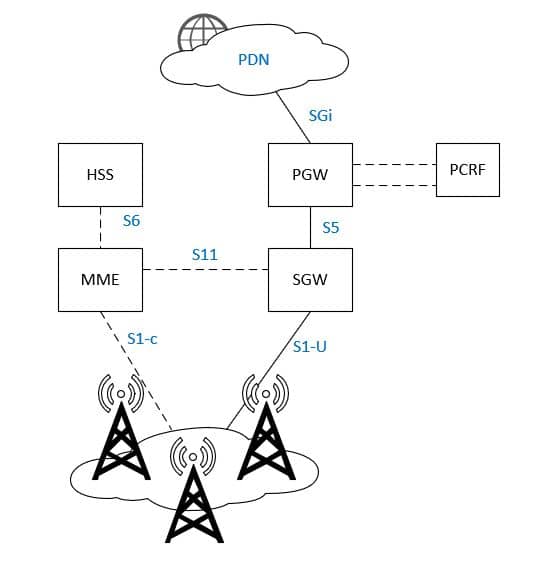
EPC Core Network
The 3G system evolved to an all-IP transport protocol that the 3GPP community called it as the EPC (Evolved Packet Core). The 3GPP community decided that the EPC would not have a circuit-switched domain anymore and that the EPC should be an evolution of the packet-switched architecture used in GPRS/UMTS.
This decision consequently require changes in core architecture and services provided will be replaced by IP-based solutions in the long-term.
EPC was first introduced by 3GPP in Release 8 standard
EPC Core Network and CUPS
The Control and User Plane Separation (CUPS) of the EPC nodes is an architecture enhancement. The separation of functionality ( Control and User plane) in the EPC’s SGW and PGW will enable flexible network deployment, operation and independent scaling between control and user plane function – i.e. without affecting the nodes that are subjected to this split.
CUPS allows for:
- Reducing Latency on application service, e.g. by selecting User plane nodes which are closer to the RAN or more appropriate for the intended UE usage type without increasing the number of control plane nodes.
- Supporting Increase of Data Traffic, by enabling to add user plane nodes without changing the number of e.g. SGW-C, PGW-C in the network.
- Locating and Scaling the CP and UP resources of the EPC nodes independently.
- Independent evolution of the CP and UP functions.
- Enabling Software Defined Networking to deliver user plane data more efficiently.

EPC towards the 5G Core
3GPP TS 23.501 specification descries the architecture of the 5G System. The 5G architecture is defined as service-based and the interaction between network functions is represented in two ways.
– A service-based representation, where network functions (e.g. AMF) within the Control Plane enables other authorized network functions to access their services. This representation also includes point-to-point reference points where necessary.
– A reference point representation, shows the interaction exist between the NF services in the network functions described by point-to-point reference point (e.g. N11) between any two network functions (e.g. AMF and SMF).
Service-based interfaces are listed in clause 4.2.6. Reference points are listed in clause 4.2.7.
Network functions within the 5GC Control Plane shall only use service-based interfaces for their interactions.
NOTE 1: The interactions between NF services within one NF are not specified in this Release of the specification.
NOTE 2: UPF does not provide any services in this Release of the specification, but can consume services provided by 5GC Control Plane NF
Functions Mapping : 4G and 5G

In comparison to the previous generation of mobile core network, the 5G technology is expected to be flexible, scalable and move to a more open implementations. The core side will consist of several network functions which will rely heavily on virtualization and cloud infrastructure.
The transition from 4G to 5G,
EPC network elements are decomposed to 5G core network functions and enabling to run as a cloud based applications
- The 4G Mobility management entity (MME) functionality is divided into : Access and Mobility management Function (AMF), session management function (SMF) and Authentication Server Function (AUSF):
- AMF receives all connections and sessions related to UE via the N1/N2 (reference) interface. It will handle the mobility and connection tasks and the messages related to session will be forwarded to the SMF via the N11 interface
- SMF handles the PDU session management
- AUSF handles the UE authentication part based on authentication vectors from Unified Data Management (which stores the UE subscription data and user-context).
- The 4G S-GW and P-GW have been divided into session management function (SMF) and user plane function (UPF):
- SMF handles the UE IP address assignment and UPF selection
- UPF acts as PDU session anchor – it is responsible for packet routing, QoS enforcement and charging functionality
Following are the new 5G core functions introduced:
- Network Slice Selection Function (NSSF): NSSF helps in setting up multiple virtual network slices of the RAN, core and transport networks to meet specific service requirements.
- Network Exposure Function (NEF): This is the capability exposure function used by the external network entities to interface with 5G core network.
- Network Repository Function (NRF): It aids the 5G services based architecture. It acts as repository of all services offered by the different network functions.
In order to support high data rates and low latency needs of 5G, the access network and fronthaul have been revamped. At the access side, the 4G eNodeB (eNB) is now called 5G gNB (next-generation node B):
- The gNB is split into two parts – gNB centralized unit (gNB-CU) and gNB distributed unit (gNB-DU). Both are connected to each other using ethernet based IP midhaul network.
- Generally, gNB-CU is virtualized and runs in context of virtualized core or virtualized edge.
- gNB-DU might be integrated with the radio head or can be virtualized and run on the edge or cloud.
5G System
5G System (5GS) consist of the following components
- Access Network (5G-AN)
- Core Network (5G-CN)
- User Equipment (UE)

5G System Architecture
5G System Architecture consist of the following components. The functional description of these network functions is described in 3GPP TS 23.501 section 6
- Authentication Server Function (AUSF)
- Access and Mobility Management Function (AMF)
- Data Network (DN), e.g. operator services, Internet access or 3rd party services
- Unstructured Data Storage Function (UDSF)
- Network Exposure Function (NEF)
- Network Repository Function (NRF)
- Network Slice Selection Function (NSSF)
- Policy Control Function (PCF)
- Session Management Function (SMF)
- Unified Data Management (UDM)
- Unified Data Repository (UDR)
- User Plane Function (UPF)
- Application Function (AF)
- User Equipment (UE)
- (Radio) Access Network ((R)AN)
- 5G-Equipment Identity Register (5G-EIR)
- Security Edge Protection Proxy (SEPP)
- Network Data Analytics Function (NWDAF)
5GC Service Based Architecture
In the 5G system, control-plane mainly uses service based interfaces (sbi) to communicate. Comparing to the traditional point-to-point connectivity where each node connected directly with definite protocol stack.
While in 5G SBI, implements a producer-consumer model where each network function offers it’s services and is not aware of clients/consumers who use them. New NF can be just be connected in the network (e.g. IP network) and with well defined services.
In case of changes in the services offered by a network function the interfaces must be updated using the common messaging layer that handles e.g. service discovery.
User-plane interaction to control-plane is through point-to-point interfaces.
Service Based Interfaces (SBI)

Non-Service Based Interfaces (SBI)

NF Service Framework
3GPP define an NF service is one type of capability exposed by NF ( NF Service Producer) to other authorized NF (NF Service Consumer) through a service-based interface. A Network Function may expose one or more NF services
Following are criteria for specifying NF services:
- NF services are derived from the system procedures that describe end-to-end functionality, where applicable (see 3GPP TS 23.502 [3], Annex B drafting rules). Services may also be defined based on information flows from
other 3GPP specifications. - System procedures can be described by a sequence of NF service invocations.
NF Service Consumer – NF Service Producer interactions
3GPP defines NF service framework follows two mechanism
- Request-Response
- Subscribe Notify

Although more than 20years working on Mobile Telecommunications – Core Network. Always wanting to learn and try new things.